1.1 VALVES
A valve is a device that regulates, controls, or directs the flow of a fluid by opening, closing, or partially obstructing fluid flow. A valve is a mechanical device that controls the flow and pressure of fluid within a system or process.
1.2 CLASSIFICATION OF VALVES

1.3 TYPES OF VALVES
1.3.1 Gate valve:

A gate valve, also known as a sluice valve, is a valve that opens by lifting a barrier (gate) out of the path of the fluid. Gate valves require very little space along the pipe axis and hardly restrict the flow of fluid when the gate is fully opened. The gate faces can be parallel but are most commonly wedge-shaped (in order to be able to apply pressure on the sealing surface).
Gate valves are mostly used with larger pipe diameters (from 2″ to the largest pipelines) since they are less complex to construct than other types of valves in large sizes.
1.3.2 Globe valve

The globe valve is used to start-stop and regulate the fluid in it. Globe stopper occurs at a place in the system where we have to control the fluid flow, and also take into account the leakage and tightness of the system.
It is costlier than gate valves. But it provides good leak-proof and tightness than gate valves. Normally the globe valves are used as a control valve.
It is also used for cooling water systems, also used in transport the fuel oil, and lube oil. Its shape is globular at the bottom side that’s why we called it a globe.
1.3.3 Needle valve

A needle valve is used to accurately control flow rates of clean gasses or fluids. The adjustments are gradual and smooth for controlling the flow rate, however, they can also be used as a reliable shut-off valve. However, they are generally only used for low flow rates and have a relatively large pressure drop from the inlet to the outlet. Common port sizes for needle valves range from 1/8” up to 2”. The most common application is to control the flow of a gas, like a propane needle valve does.
Needle valves open and close an orifice with a tapered end that raises and lowers with the spin of a handle. Figure shows a needle valve cross sectional view, design, and components. The handle is connected to the plunger, also called a stem. When you turn the handle, the plunger moves up or down based on the threads. The locking nut prevents it from fully unscrewing. As the plunger moves down, the tapered pointed end comes into contact with the valve seat to fully seal the orifice.
1.3.4 Butterfly valve:

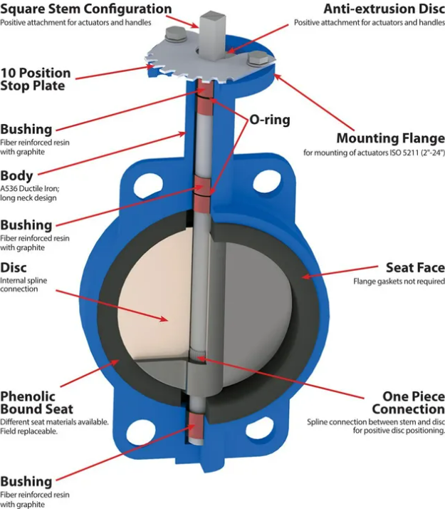
A butterfly valve is from a family of valves called quarter-turn valves. In operation, the valve is fully open or closed when the disc is rotated a quarter turn. The “butterfly” is a metal disc mounted on a rod. When the valve is closed, the disc is turned so that it completely blocks off the passageway. When the valve is fully open, the disc is rotated a quarter turn so that it allows an almost unrestricted passage of the fluid. The valve may also be opened incrementally to throttle flow.
1.3.5 Ball Valve

A Ball valve is a quarter-turn rotary motion valve that uses a ball-shaped disk to stop or start the flow. Most ball valves are of the quick-acting type, which requires a 90° turn of the valve handle to operate the valve. The ball valve is Smaller and lighter than a gate valve of the same size and rating.
1.3.6 Plug valve

Plug valve is a Quarter-turn rotary motion Valve that uses a tapered or cylindrical plug to stop or start the flow. The disk is in plug shape, which has a passage to pass the flow. Plug valve used as on-off stop valves and capable of providing bubble-tight shutoff. Plug valve can be used in a vacuum to high-pressure & temperature applications.
1.3.7 Pinch Valve

The pinch valve is also known as a clamp valve. It is a linear motion valve. Used to start, regulate, and stop fluid flow. It uses a rubber tube, also known as a pinch tube, and a pinch mechanism to control the fluid. Pinch Valve is ideally suited for the handling of slurries, liquids with large amounts of suspended solids, and systems that convey solid material pneumatically
1.3.8 Non-return valve

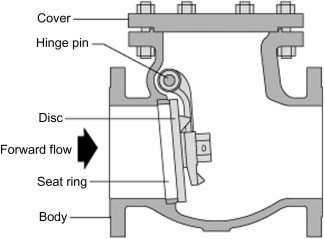
A non-return valve allows a medium to flow in only one direction and is fitted to ensure that the medium flows through a pipe in the right direction, where pressure conditions may otherwise cause reversed flow. The flow through the non-return valve causes a relatively large pressure drop, which has to be taken into account when designing the system.
There are different types of non-return valves, such as spring-loaded, swing type, and clapper type valves. Non-return valves are for example used with mixing loops in heating and cooling systems to ensure proper operation, and with domestic water systems to prevent backflow
1.3.9 Pressure relief valve

A pressure Relief Valve is a safety device designed to protect a pressurized vessel or system during an overpressure event.
An overpressure event refers to any condition which would cause pressure in a vessel or system to increase beyond the specified design pressure or maximum allowable working pressure (MAWP).
The primary purpose of a pressure Relief Valve is protection of life and property by venting fluid from an over pressurized vessel.
Many electronic, pneumatic and hydraulic systems exist today to control fluid system variables, such as pressure, temperature and flow. Each of these systems requires a power source of some type, such as electricity or compressed air in order to operate. A pressure Relief Valve must be capable of operating at all times, especially during a period of power failure when system controls are nonfunctional.
The pressure Relief Valve must open at a predetermined set pressure, flow a rated capacity at a specified overpressure, and close when the system pressure has returned to a safe level. Pressure Relief Valves must be designed with materials compatible with many process fluids from simple air and water to the most corrosive media. They must also be designed to operate in a consistently smooth and stable manner on a variety of fluids and fluid phases.

